
What is Behind ETABS's Simplified C- T- Shear wall Design
- Adisorn O.
- May 14, 2025
- 3 min read

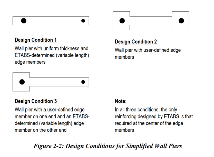
Based on the Shear Wall Design Manual (ACI 318-19), the Simplified C- and T-section shear wall design (Chapter 2.1.1, pages 2-2 to 2-8) involves:
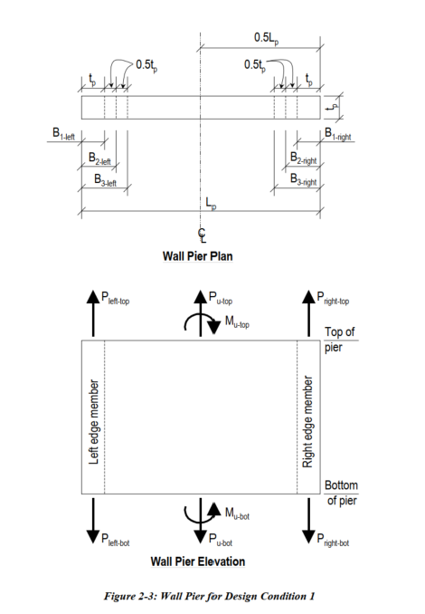
Decomposing the applied axial force (Pu) and moment (Mu) into equivalent axial loads on left and right edge members.
Iteratively sizing the edge member length (B1) until the required steel area (Ast, Asc) is within max allowed ratios (PTmax, PCmax).
Limiting B1 such that B1 ≤ Lp/2.
INPUT:
  Pu       → axial force on the pier (N or kN)

    Mu       → moment on the pier (N·mm or kN·m)

    Lp       → total horizontal length of pier (mm or m)

    tp       → thickness of wall (mm or m)

    fc       → concrete strength (MPa)

    fy       → steel yield strength (MPa)

    phi      → strength reduction factor

    PTmax    → max tension steel ratio (e.g., 0.025)

    PCmax    → max compression steel ratio (e.g., 0.02)


CONVERT all inputs to consistent units (N, mm)

SET:

    B1 = tp               → initial edge length

    max_B1 = Lp / 2       → upper bound per ACI

WHILE B1 <= max_B1:

    COMPUTE:

        P_left  = Pu/2 + Mu / (Lp - B1)

        P_right = Pu/2 - Mu / (Lp - B1)


    FOR EACH EDGE (left and right):

        IF edge axial force < 0 (tension):

            Ast = |P| / (phi * fy)

            Asc = 0

        ELSE (compression):

            Ag = B1 * tp

            Asc = max( (P - 0.85 * fc * Ag) / (phi * fy), 0 )

            Ast = 0


    CHECK:

        Ast ≤ PTmax * B1 * tp

        Asc ≤ PCmax * B1 * tp


    IF both edges pass:

        REPORT:

            Success with current B1

            Required Ast and Asc per edge

        EXIT


    ELSE:

        INCREMENT B1 by 0.5 * tp


REPORT:

    "Design failed: Steel demand exceeds max allowed even at max B1"
Here's a MATLAB example script that automates this simplified design logic for a planar T-wall section:
MATLAB Sample: Simplified C/T Shear Wall Design
% Given a wall with:
% - Pu = 1500 kN, Mu = 400 kN.m
% - Lp = 4 m, tp = 0.25 m
% - fc = 35 MPa, fy = 500 MPa
% - phi = 0.9, PTmax = 0.025, PCmax = 0.02

design_CT_wall(1500, 5000, 4, 0.25, 35, 500, 0.9, 0.025, 0.02);

function design_CT_wall(Pu, Mu, Lp, tp, fc, fy, phi, PTmax, PCmax)
% Simplified T- or C-wall design: ACI 318-19 based
% Inputs:
% Pu, Mu     - factored axial force (N), moment (N.m)
% Lp, tp     - wall length (m), thickness (m)
% fc, fy     - concrete strength (MPa), steel yield strength (MPa)
% phi        - strength reduction factor
% PTmax, PCmax - max steel ratios

% Convert to consistent units (N, mm)
Pu = Pu * 1e3; Mu = Mu * 1e6;  % to N and N.mm
Lp = Lp * 1e3; tp = tp * 1e3;

% Start iteration with edge member B1 = tp
B1 = tp;
maxB1 = Lp / 2;

while B1 <= maxB1
    % Step 1: Equivalent axial forces at edges
    P_left = Pu/2 + Mu / (Lp - B1 );
    P_right = Pu/2 - Mu / (Lp - B1);

    % Step 2: Design steel areas at both edges
    % Initialize steel requirements
    Ast_left = 0; Asc_left = 0; Ast_right = 0; Asc_right = 0;

    % Left edge
    if P_left < 0  % tension
        Ast_left = abs(P_left) / (phi * fy ); % mm^2
    else  % compression
        Ag = B1 * tp;
        Asc_left = (P_left - 0.85 * fc * Ag) / (phi * fy );
    end

    % Right edge
    if P_right < 0
        Ast_right = abs(P_right) / (phi * fy );
    else
        Ag = B1 * tp;
        Asc_right = (P_right - 0.85 * fc * Ag) / (phi * fy );
    end
    Asc_left = max(0, Asc_left);
    Asc_right = max(0, Asc_right);

    % Step 3: Check against max ratios
    Ast_max = PTmax * B1 * tp;
    Asc_max = PCmax * B1 * tp;

    if Ast_left <= Ast_max && Asc_left <= Asc_max && ...
       Ast_right <= Ast_max && Asc_right <= Asc_max
        fprintf('\n=== Final Design ===\n');
        fprintf('Edge Member Width (B1): %.1f mm\n', B1);
        fprintf('Left Edge: Ast = %.1f mm², Asc = %.1f mm²\n', Ast_left, Asc_left);
        fprintf('Right Edge: Ast = %.1f mm², Asc = %.1f mm²\n', Ast_right, Asc_right);
        return
    end

    % Increment B1
    B1 = B1 + 0.5 * tp;
end

disp('Design failed: Required reinforcement exceeds limit even at max edge width.');
end
Output Explanation:
It iteratively increases the edge leg size B1 (starting from tp) until reinforcement demands are within limits.
Computes and prints required tension (Ast) and compression (Asc) areas at each edge.
