
EASY-TANK™: Automated Finite Element Modeling of Underground Reinforced Concrete Shells
- Adisorn O.
- Jun 10
- 6 min read

Updated: Jun 16
Adisorn Owatsiriwong
ALPS CONSULTANTS
Introduction
Underground reinforced concrete tanks are among the most common structures encountered in industrial, infrastructure, water treatment, wastewater treatment, fuel storage, and utility projects. Despite their apparent simplicity, their structural behavior can be surprisingly complex.
A typical underground tank consists of:
- Base slab
- Side walls
- Top slab
- Internal partitions
- Pile-supported foundation system
- Soil and groundwater loading
-Surcharges, buoyancy force

The interaction between these components often requires finite element analysis (FEM) to obtain realistic internal forces and deformations.
In commercial FEM software, engineers must manually create geometry, define mesh density, insert supports, assign loads, generate combinations, run staged construction analysis, and review results. While this process is manageable for a single project, it becomes repetitive and time-consuming when multiple design iterations are required.
To address this challenge, we developed EASY-TANK™, a specialized finite element modeling and optimization tool for rectangular underground tanks.
The philosophy behind EASY-TANK™ is simple:
Engineers should focus on engineering decisions, not on repetitive model preparation and result interpretation.

Instead of manually constructing FEM models, users only provide a limited set of engineering parameters such as tank dimensions, wall thicknesses, pile locations, material properties, and loading conditions. The software automatically generates the complete finite element model, performs analysis, and can further optimize the structural dimensions.
This significantly reduces modeling effort while maintaining engineering rigor.
---

Reissner-Mindlin Shell Formulation
Why Reissner-Mindlin Shell?
Underground tanks typically have relatively thick slabs and walls compared with conventional building floor systems.
For such structures:
- Transverse shear deformation becomes important.
- Classical thin-shell theory may underestimate deflections.
- Thick slab behavior must be captured.
For these reasons, EASY-TANK™ employs a Reissner-Mindlin (RM) shell formulation.
The element contains:
- Membrane behavior
- Plate bending behavior
- Transverse shear behavior
with nodal degrees of freedom in local coordinates:
- u = translation in +x
- v = translation in +y
- w = translation in +z
- rx = rotation about +x
- ry = rotation about +y
- rz = drilling rotation +z
The formulation is particularly suitable for reinforced concrete tank structures where both membrane and bending actions contribute significantly to the overall response.

Stiffness Matrix Formulation


2x2 Gauss quadrature is used for integration

Drilling Degree of Freedom Stabilization
One challenge in shell finite elements is the presence of the drilling degree of freedom:
θz
This rotational degree of freedom does not possess a natural strain energy term in standard shell formulations.
Without treatment, the element stiffness matrix becomes rank deficient, leading to numerical instability and singular global stiffness matrices.
To overcome this issue, EASY-TANK™ introduces a stabilization mechanism through a small artificial drilling stiffness.
Conceptually:
Kdrill = α
α = small stabilization coefficient
The stabilization stiffness is intentionally chosen to be several orders of magnitude smaller than the physical bending stiffness.
As a result:
- Numerical stability is achieved.
- Matrix singularities are avoided.
- Structural response remains essentially unaffected.
This technique is widely used in practical shell finite element implementations and provides a robust solution for large-scale shell models.
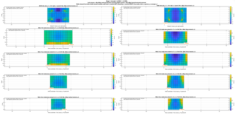
Wood-Armer Moment
At any infinitesimal area cut, the moment can be written as 2nd order tensor like stress tensor, i.e.
m = [mxx mxy; mxy myy]
By eigenvalue analysis, we can find the principal directions and magnitudes of the principal moments where mxy = 0, i.e.
m = [m11 0; 0 m22]; where m11 and m22 are bending moment in the principal directions.
For slab near the entrant corner, column and wall support where both mx and my act simultaneously. mxy is low value at most typical slab region.
For reinforcement design, it is common to design the rebar align to the local x and y direction of slab for ease of construction. Wood-Armer's moment was originated from that practical design aspect by considering that twisting moment must increase to normal bending moment in a conservative sense, i.e.
mx_design = mx + |mxy| ; mx > 0
= mx - |mxy| ; mx < o and the same to my_design
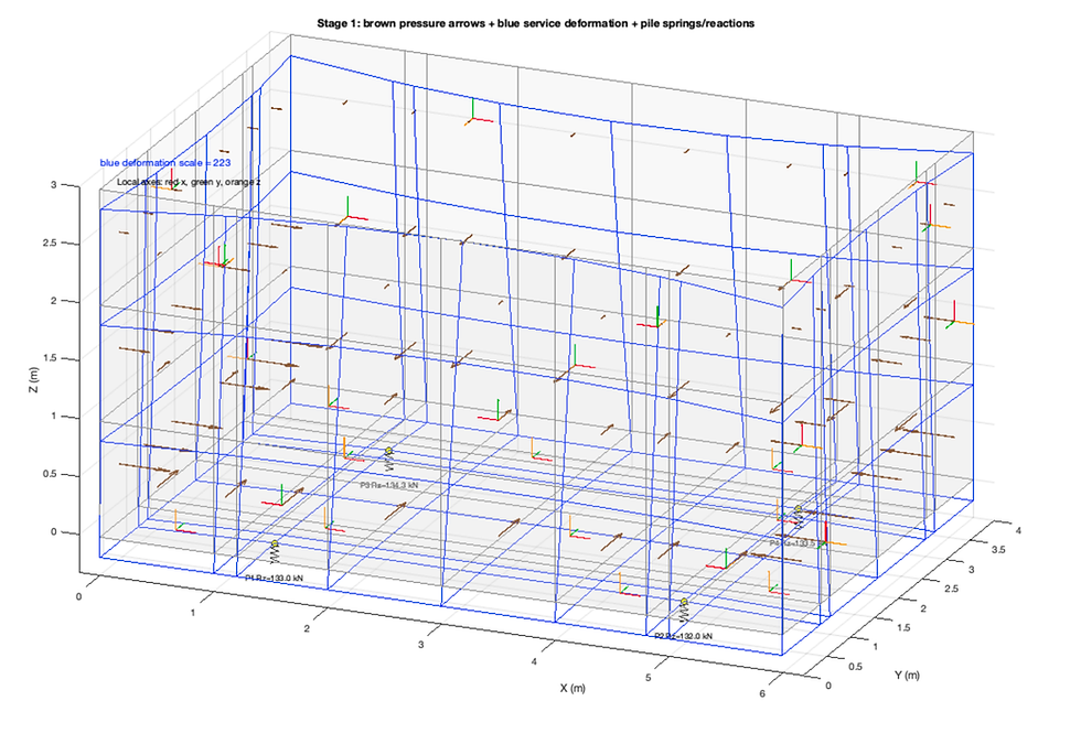
Automated Stage Construction Analysis
Underground tanks experience different structural conditions during construction and operation.
A single analysis often fails to capture these changing load paths.
EASY-TANK™ therefore supports staged construction analysis.
## Stage 1 – Empty Tank Construction Condition
The first stage represents the condition immediately after construction.
Typical loads include:
- Self-weight of slabs
- Self-weight of walls
- Backfill soil pressure
- Groundwater pressure
No internal liquid pressure is applied.
This stage is important because:
- Wall bending moments may be governed by external soil pressure.
- Base slab uplift may occur due to groundwater.
- Construction stresses may exceed operational stresses in some regions.
---
## Stage 2 – Operational Condition
The second stage represents the tank in service.
Additional loads include:
- Internal liquid pressure
- Stored water or fuel weight
- Hydrostatic loading on walls
- Hydrostatic loading on base slab
The final response is obtained by combining the stress history from Stage 1 and Stage 2.
This approach more accurately represents actual structural behavior than applying all loads simultaneously.

Adaptive Mesh Generation and Pile Node Insertion
One common difficulty in automated tank modeling is handling pile-supported foundations.
Pile locations are often irregular and do not coincide with the initial shell mesh.
If pile supports are simply connected to the nearest node:
- Support eccentricities occur.
- Load transfer errors increase.
- Local force concentrations become inaccurate.
To solve this problem, EASY-TANK™ automatically inserts mesh lines passing through pile locations.
The process is:
1. Generate base structured mesh.
2. Extract pile coordinates.
3. Insert additional mesh lines at pile X and Y locations.
4. Rebuild mesh topology.
5. Regenerate shell elements.
As a result:
- Every pile coincides with a shell node.
- Support springs connect directly to structural nodes.
- No interpolation or rigid-link approximation is required.
This technique significantly improves support modeling accuracy while preserving an automated workflow.
Multi-Cell Generator and Template
With a powerful GUI, a cellular tank can be generated and analyse at a glance. This turns EASY-TANK from a shell solver to a sophisticated design tool that saves hours of modeling and analysis work.


Design Optimization
Beyond finite element analysis, EASY-TANK™ incorporates numerical optimization.
Traditional design typically follows:
1. Assume dimensions.
2. Analyze.
3. Check stresses.
4. Revise dimensions.
5. Repeat.
This trial-and-error process can require many iterations.
Optimization automates this procedure.
---
Design Variables
Typical optimization variables include:
- Base slab thickness
- Wall thickness
- Top slab thickness
- Internal wall thickness
- Concrete strength
- Pile arrangement parameters
---
Objective Function
The primary objective is minimizing material volume.
Mathematically:
Minimize
V = Σ(Ai × ti)
where:
- Ai = structural component area
- ti = component thickness
For reinforced concrete tanks, minimizing volume generally correlates well with minimizing cost.
---
Constraints
Optimization is performed subject to:
### Strength Constraints
- Flexural capacity
- Shear capacity
- Punching shear
- Bearing pressure
### Serviceability Constraints
- Deflection limits
- Crack control requirements
### Geometric Constraints
- Minimum thickness
- Practical construction limits
Only solutions satisfying all constraints are accepted.
The optimization engine then searches for the most economical design configuration.
---
Future Extensions
Although EASY-TANK™ already automates FEM generation and optimization, several future developments are planned.
## Reinforcement Optimization
Current optimization focuses primarily on geometry.
Future versions may optimize:
- Bar spacing
- Bar diameter
- Layer arrangement
to minimize total reinforcement weight.
---
## Soil-Structure Interaction
Future developments may include:
- Winkler soil springs
- Continuum soil models
- Nonlinear soil behavior
for improved foundation modeling.
---
## Construction Sequence Simulation
More advanced staging may include:
- Excavation sequence
- Dewatering effects
- Progressive backfilling
- Sequential wall casting
allowing realistic construction simulations.
---
## Reliability-Based Design
Future versions may incorporate:
- Probabilistic loading
- Material uncertainty
- Reliability indices
- Risk-based optimization
to provide more rational designs than deterministic approaches.
---
## AI-Assisted Design Automation
One long-term vision for EASY-TANK is integration with AI-driven engineering workflows.
Potential capabilities include:
- Automatic design review
- Intelligent mesh control
- Optimization strategy selection
- Automatic report generation
- Design recommendation systems
This transforms the software from a numerical solver into an engineering decision-support platform.
---
Conclusion
EASY-TANK demonstrates how specialized finite element automation can significantly improve engineering productivity.
By combining:
- Automated Reissner-Mindlin shell modeling
- Robust drilling DOF stabilization
- Adaptive pile-node meshing
- Staged construction analysis
- Numerical optimization
The software allows engineers to focus on design decisions rather than repetitive FEM model preparation.
As the platform evolves, future integration of advanced optimization, soil-structure interaction, reliability analysis, and AI-assisted decision making will further enhance its capabilities.
The ultimate goal is not merely to analyze underground tanks faster, but to create a practical engineering environment where analysis, design, and optimization operate seamlessly within a single workflow.